1969, Model & Allied Publications
Sorry, out of stock, but click image to access prebuilt Amazon search for this title!
Alternative online retailers to try:
Click here to access our prebuilt search for this title on Abebooks
Or click here to access our prebuilt search for this title on Alibris
Or click here to access our prebuilt search for this title on Ebay


|
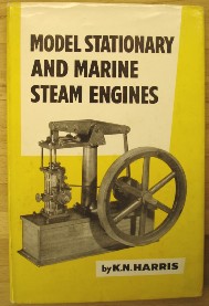
- Model Stationary and Marine Steam Engines [top]
First published in 1958 in Great Britain in hardcover
Reprinted in 1964 in an enlarged and revised edition
Reprinted in 1969 by Model & Allied Publications in hardcover with dustjacket, 154pp, original UK retail price of 18/- (18 shillings)
Contents: K.N. Harris had more than 60 years experience as a model engineer and spent the first 20 yrs of his working life constructing, erecting, testing, maintaining and designing a wide variety of steam engines. He has applied that experience to model steam engines. Here, different types of model are reviewed from oscillating types to high-duty marine and small-power enclosed engines. The illustrations are mostly of engines built by the author.
The book covers reversing gears, lubrication, governors, lagging, splash guards, drain cocks, feed pumps, stop valves, saddle keys, etc. The book is described as a "must" for serious model engineers who strive for perfection and that essential creative approach!
Chapters:
- Fundamental principles of working
- Oscillating engines
- Simple fixed cylinder engines
- A simple vertical engine
- Compound engines
- A horizontal mill engine
- A single cylinder twin screw engine
- Enclosed types of steam engine
- A pinnace type engine
- A single cylinder high duty marine engine
- A 3 in. scale launch engine
- Twin oscillating paddle engines
- Cylinder design and construction
- Condensing
- Reversing gears
- Lubrication
- Governors
- Miscellaneous (governors, lagging, splash guards, draincocks, feed pumps, stop valves, saddle keys, nuts, bolts, setscrews and studs, locknuts, painting, finish, forcing screws)
- Testing model engines
- Twin non-condensing launch engine
Bibliography; Index
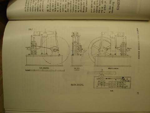
Sample Page: The Beam Engine
|
|
2000, TEE Publishing, pbk
In stock, click to buy for £16.70, not including post and packing
1982, Argus Books Ltd
Sorry, sold out, click image to access prebuilt search for this title on Amazon
1972, Model & Allied Publications, hbk
In stock, click image above to buy for £12.99, exc. p&p
1967, Model & Allied Publications
Sorry, this particular edition has sold out, but click image to access prebuilt search for this title on Amazon
Alternative online retailers to try:
Click here to access our prebuilt search for this title on Abebooks
Or click here to access our prebuilt search for this title on Alibris
Or click here to access our prebuilt search for this title on Ebay
|
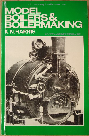
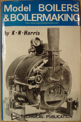
- Model Boilers & Boilermaking [top]
Foreword by Edgar T. Westbury
First published in 1967 in Great Britain by Model & Allied Publications in hardback, with dustjacket, 188pp, No ISBN in Great Britain by Model & Allied Publications in hardback, with dustjacket, 188pp, No ISBN
Published in 1967 in Great Britain by Model Aeronautical Press in hardback with dustjacket, 185pp, No ISBN
Reprinted in 1971 in hardback with dustjacket, 188pp, No ISBN (2nd impression) in hardback with dustjacket, 188pp, No ISBN (2nd impression)
Reprinted in 1972 in hardback with dustjacket, 188pp, No ISBN (3rd impression)
Reprinted in 1974 in paperback
Reprinted in 1974 in paperback for a second time (fifth impression)
Reprinted in 1976 in paperback, 186pp, ISBN 0852423772
Reprinted in 1977 in paperback (seventh impression) details as per 1976 edition. Original UK retail price: £2.50 Net.
Reprinted in 1980 in paperback (eighth impression)
Reprinted in 1982
in Great Britain by Argus Books Ltd, in paperback, revised edition, 185pp, ISBN 0852423772. (Revised and updated by Martin Evans)
Reprinted in 2000 in Great Britain by TEE Publishing in paperback, 185pp, ISBN 1857611144
This was believed to be the first book dealing exclusively and comprehensively with model boilermaking apart from a book in the basic, but practical Model Engineer series published in the early days of model engineering (pre-1967).
Around the turn of the century, E. L. Pearce's 'Model Boilermaking' handbook first appeared; this book therefore is an attempt to update that work and considerably expand it.
K.N. Harris was a practical engineer with a lifetime of experience in both full-size and model steam engines when he wrote this work and it gives reliable guidance on the design and construction of all types of small boilers. It is a fitting companion to the book Model Stationary & Marine Steam Engines, also by K.N. Harris.
Experienced model engineers often express different opinions on the details of boiler design and how to construct them. However, they all agree on the same point-that there is a need for ample strength in the complete fabricated structure to withstand the maximum pressure every likely to be encountered for the particular conditions of working. This issue is given considerable space in Chapter Two, and tests to ensure proper margins of safety are discussed in Chapter Seven. Whether boilers are made by riveting, brazing or other methods, these safety measures should be carefully observed.
Harris states in his introduction that he has tried to provide information and data that will enable any intelligent model engineer to design and build a safe, working, model boiler, efficient for its purpose. He acknowledges debt owed to the work of E. L. Pearce, Henry Greenly, James Crebbin ("Uncle Jim"), Mr. C.M. Keiller for his work on locomotive boiler, tube, flue and superheater proportions and to Messrs Johnson Matthey & Co. Ltd for their advice on silver solders.
Contents:
Chapter One
General Considerations; Fundamental principles of functioning; Combusion and evaporation; Efficiency of model boilers; Primary features of design to produce an efficient boiler; notes on "scale" and its effect in model work
Chapter Two
Constructional materials and their physical properties; calculations relating to safe working pressures; General relative proportions (structural).
Materials, calculations relating to safe working pressures, general data on design
Chapter Three
Types of Boilers
Chapter Four
Practical methods of construction; Flanging and forming plates; Setting out; Annealing; Riveting
Chapter Five
Fuels and firing methods
Chapter Six
Boiler mountings and fitting; Safety valves; water gauges; pressure gauges; stop valves; steam fountains; clack valves; blow-down valves, regulators; domes; steam collectors; separators
Chapter Seven
Testing Model Boilers; Test pressures; Methods of Testing
Chapter Eight
Tube Proportions; Spacing and layout; Superheaters and feedwater heaters
Chapter Nine
Model locomotive-type boilers
Appendix. Boiler Designs
Tables
1. Properties of saturated steam
2. Calorific values of various fuels
3. Tube circumferences and surface areas, etc
4. Gauges and weights of sheet copper
5. Recommended screw threads for pipes and fittings
6. Strength of round copper stays
7. Safety valve sizes
8. Properties of J.M.C silver brazing alloys
9. Boiler evaporation figures
DRAWINGS AND SKETCHES
2-1 " Waisted " stay, head dotted
2-2 "Threaded " stay
2-3 " Gusset " stay
2-4 Single butt riveted and brazed joints
2-5 Double butt riveted and brazed joints
2-6 Double riveted lap joint
3-1 Plain horizontal " Pot " loop superheater
3-1 A, B, C " Hedgehog " vertical flue tube. Water tubes
3-2 Horizontal, sloping flues
3-3 " Wedge " multidrum.
3-4 Externally fired return tube boiler with superheater
3-5 Vertical centre flue, no firebox
3-6 Vertical centre flue large with cross tubes.
3-7 Vertical multitubular
3-8 Section field tube
3-9 Vertical field tube, no firebox, " crowned " bottom
3-9 Vertical field tube with firebox
3-10 Stanley multitubular
3-11 Cornish
3-12 Centre flue, model type, cross tubes
3-13 Scotch marine dryback
3-13A & B Three furnace wetbacks. Ditto double ended
3-13C Inglis modification
3-14 Lancashire
3-15 Galloway
3-15A Horizontal multitubular
3-16 Vertical centre flue
3-17 Vertical multitubular
3-18 Multitubular submerged tubes
3-19 Cochran
3-20 Robertson
3-20A Combined fire and water tube
3-21 Saddle
3-22 Napier-Haystack
3-22A Bolted construction
3-23 Water tube annular feeders
3-24 Annular firetube
3-25 Sentinel
3-26 Fire engine
3-27 Lune Valley
3-27A Lune Valley, modified, raised drum
3-28 Bolsover Express
3-28A Illingworth
3-29 Clarkson
3-31 Yarrow
3-32 Babcock
3-33 Niclausse
3-34 Bottom feeder for Yarrow
3-35 Paris
4-1 Method of setting out G.W. taper barrel
4-2 Method of setting out cone barrel
4-3 Method of setting out circular tube plate
4-4 Firebox wrapper plate
4-5 Firebox wrapper plate sloped type
4-6 Layout of Belpaire throatplate.
4-7 Belpaire plate with allowance for " draw."
4-8 Taper nosed mallet
4-9 Steps in forming rivets
4-10 Tapered inner firebox
4-11 Plate after first flanging
4-11A Detail of former and backing strip
4-12 Caulking or light riveting hammer
4-13 Brazing set-up
4-14 Coppersmiths' joint enlarged detail
4-15 Dollies
4-16 Punches and snaps
4-17 Effect of stretching on rivet holes
4-18 Longitudinal stay arrangement
4-19 Stay with rounded face nut
4-20 Manholes
5-1 Simple " bars " gas burner
5-2 Pressure start for fuel control
5-3 Thermostat, fuel control
5-4 Controlled air supply for meth burner
5-5 Annular meth burner
5-6 Cooling fins on spirit supply pipe.
5-7 Special spirit burner.
5-8 Complete lamp and tank layout
5-8A Standard type of jet.
5-9 Petrol and paraffin roarer burners
5-10 Needle jet control
5-11 Palmer spray burner
5-12 Application to loco firebox of above
5-13 Arrangement of boiler arch and deflector, arch tubes, dampers, etc
6-1 Salter spring balance
6-2 Deadweight safety valve
6-3 Semi-pop, ball valve
6-4 " Pop " safety valve, enlarged valve and seating
6-5 Double sided plate water gauge
6-6 " Standard " water gauge
6-7 " One Piece " plain water gauge
6-8 " One Piece " 3-valve water gauge
6-9 " Meyer " gauge
6-10 Gauge with glass sealed by end-washers
6-11 A common type as German models in 1900s
6-12 Check valve with shut-off
6-13 Twin top feed fitting
6-14 Method of seating ball valve and alternative forms of seating
6-15 Screw down valve, " straight thro "
6-15 Stroudley type regulator
6-17 Slide type loco regulator
6-18 Screw down " angle " valve
6-19 Slide type loco smokebox regulator
6-20 Poppet valve regulator
6-21 Siphon and shut-off cock
6-22 " Solid " dome
6-23 Dismantling dome
6-24 Screw down blowdown valve
7-1 Thermometer adaptor for test
7-2 Steam separator.
8-1 Tube layout for circular tube plates
8-2 Tube layout Scotch marine
8-3 Position of tube in tube plate
8-4 Smokebox gridiron superheater
8-5 Smokebox hairpin superheater
8-6 Contra flow principle feedheater
8-7 Coil type exhaust feedheater
8-8 Contra flow principle feedheater
9-1 Former for bottom feeders of Yarrow boiler
List of Plates
1. Vertical multitubular boiler with injector feed. Note splendid workmanship and finish.
2. " Scotch " Marine boiler with Donkey feed pump and an excellent range of fittings. Note : Door to smokebox with chain to hold it open. Note also how awkward it is to find convenient room for water gauge. A very fine piece of boilermaking.
3. Locomotive firebox showing sif-bronzed foundation ring.
4. Above. Small centre-flue marine boiler with blow lamp and pressure fuel tank.
5. Left. Vertical multitubular test boiler for gas firing, with loop superheater, double window plate glass water gauge, steam fountain, main stop valve, direct loaded and lever weight safety valves. Smokehood in foreground, with parts of gas burner.
7. Below. ' Model Engineer' Test boiler with alternative means of firing.
6. Above. Vertical solid fuel fired test boiler, built by J. Merrit, to E. T. Westbury's design. Note wood strip lagging.
8. Right. Return-flue Marine boiler, showing fittings.
9. Below. Marine boiler with two large return flues.
10- 11. .} Dis-assembled parts for locomotive boiler, for an American engine.
12. Above. Locomotive boiler with test pressure gauge in place.
13. Right. Top view of locomotive boiler by Martin Evans with Belpaire firebox; note seating for safety valve and top-feed connections.
14. " Smithies " type inner boiler. Note superheater and blower pipe and jet.
15. Marine centre flue type with blowlamp.
16. Locomotive Boiler, ready for fitting front tubeplate.
17. Group of fittings and mountings for test boiler.
18. Above. Inner firebox with plate girder stays.
19. Below. Inner firebox wrapper with tubeplate.
20. Locomotive boiler with wide Belpaire firebox and sloping throatplate and backhead.
21. Horizontal internally fired boiler and vaporising spirit lamp.
22. Backhead for a 11 in. gauge Pacific locomotive built by the late Karl Meyer. Note the one piece body water gauge and the centre hand pressure gauge, which is only in. dia. over the casing and was made by the constructor. This picture shows that even with such a tiny locomotive it is perfectly possible to obtain a good layout and proportionate fittings.
23. Complete firebox with girder roof stays, backhead, front tubeplate and throatplate for 1¾ in. scale narrow gauge model locomotive. The throatplate flange fits outside the barrel.
24. Inside view of firebox : note the lower part of the backhead shows a deepening piece added using a coppersmith's joint. Inside the firebox can be seen a security circulator.
25. A special type of watertube boiler for a steam car (full-size, not a model) shown partly tubed. To be fired from the top with a spray-burner.
26. Inner firebox backplate with firehole ring brazed in place.
27. Nicholson thermic syphon fitted to locomotive inner firebox, made by Martin Evans |
Other books on Model Boilers:
Other Books on Model Engineering
Books on Lathes:
Model Steam Locomotives:
Live Steam Models:
|