Model Railway Building: Baseboards, Scenery, Scratchbuilding and Landscape
| Related Model Railway Author Pages of Interest: |
Related Model Railway Topic Areas Pages of Interest: |
|
|
|
| In Pictures: |
****Hyperlinked titles will take you to our copy on sale or prebuilt searches of copies on sale****
Useful Links:
Books on Ebay-see our specially prebuilt search below
Titles to Look Out For:
[in alphabetical order, dated to earliest edition. Each listing includes later editions and printings]
1993. The Building of Platt Lane 1. Baseboard Basics and Making Tracks
1994. The Building of Platt Lane 2. Creating The Scenic Landscape
1995. The Building of Platt Lane 3. Locomotive and Rolling-Stock Construction
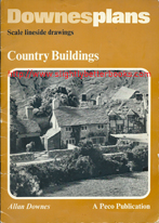
1977. Country Buildings (Downesplans: Scale Lineside Drawings) by Allan Downes
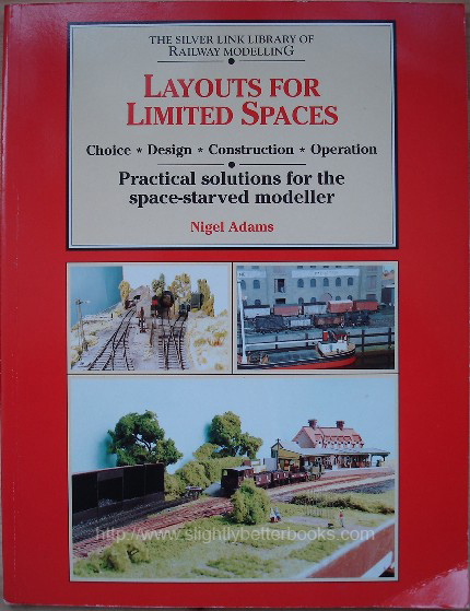
1996. Layouts for Limited Spaces: Choice, Design, Construction, Operation. By Nigel Adams
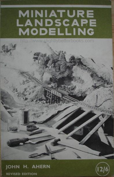
1951. Miniature Landscape Modelling by John H. Ahern
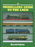
1987. Modellers' Guide to the LNER by David Adair
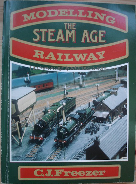
1990. Modelling the Steam Age Railway by C. J. Freezer
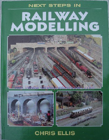
2004. Next Steps In Railway Modelling by Chris Ellis
1947. New Developments in Railway Modelling by Edward Beal
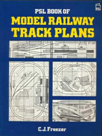
1998. PSL Book of Model Railway Track Plans by C. J. Freezer
1989. The Railway Modeller Book of 60 Plans for Small Locations
1996. The Railway Modeller Book of N Gauge Track Plans by C. J. Freezer
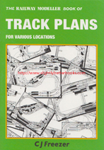
1989. The Railway Modeller Book of Track Plans for Various Locations
1979. Railway Modelling: An Introduction by W. A. Corkill
1964-1970. Track Plans by C. J. Freezer
1978. Wheel Specifications for the Modeller by Mike Sharman |
On Amazon: |
1977, Peco, pbk
In stock, click image above to buy for £6.00, not including post and packing
Alternative online retailers to try:
Click here to access our prebuilt search for this title on Abebooks
Click here to access our prebuilt search for this title on Alibris
Click here to access our prebuilt search for this title on Ebay to access our prebuilt search for this title on Ebay
Click here to access our prebuilt search for this title on Biblio |
About this book: The 4mm scale drawings in this book are basic outline plans of various buildings & are intended to assist the modeller with a desire for scratchbuilding, especially those who might find it difficult to come to terms with building dimensions in general. However, familiarity will breed experience & after reaching an understanding about dimensions that cannot usually be termed as 'standard' but more as 'proportionate' then the modeller will find it much easier in planning out his own buildings. A building basically is not much more than four walls and a roof and its character lies in the little 'bits and pieces' struck on afterwards, although in some cases one would strongly suspect as an afterthought! Dormers, porches, extensions, etc., the type of windows used, the actual wall finish - brick, stone, flint, and so on makes the building what it is and, if two buildings were made from any one plan in the book then finished off in two entirely different wall finishes - possibly a bay window added for distinction - then all that would remain identical would be the basic outline. The two buildings apart from this would be as different as chalk and cheese. Constructional methods may vary and, of course, every modeller will have his own preferences as to what materials to model with. The buildings shown in the photographs are all made from 1 millimetre card which the author believes is as good as any.
Buildings modelled (scale diagrams):
-Village Forge - a whitewashed flint or stone building with a rambling village character
-Detached Cottage - an attractive brick and pebble-dash building
-Large Country House - finished in brick & flint, this model provides a charming space filler
-Small Village Shop - single - a gabled building with three distinct wall finishes & slated roof
-Village Shops - double - an uneven tiled roof, whitewashed brick and pebble-dash finish, which adds to the charm of these typical village shops
-Watermill - imagination is the key to this attractive riverside scene
-Tudor Style Public House - delightful period house with characteristic timber framing
-Farmhouse and Barn - stone built with barn attached, an ideal countryside feature for your layout
-Farm Outbuilding - simple timber built outbuildings
-Timber Yard - a model that provides a Lineside Industry for your layout
Notes on Construction - brief description of modelling techniques, materials and their uses |
|
1996. Silver Link Publishing
In stock, click to buy for £8.55, not including p&p
Alternative online retailers to try:
Click here to access our prebuilt search for this title on Abebooks
Click here for our prebuilt search for any edition of this title on Alibris
Click here to access our prebuilt search for this title on Ebay


|
- Layouts for Limited Spaces: Choice, Design, Construction, Operation [top]
Written by Nigel Adams; Drawings by Peter Honeybone; Photographs by Martin Hewitt; Proof-reading by John Raybould; Typing by Sue Temple
First published in September 1996 in Great Britain by Silver Link Publishing in 'The Silver Link Library of Railway Modelling' series, paperback, 128pp
Original UK retail price: £14.99, ISBN 1857940555
Reprinted in July 1997 (still at £14.99), 1998, 1999 and 2001 (same details as 1996 edition).
Original UK retail price of 2001 edition: £15.99
Contents/synopsis:
This now scarce title attempts to address a common problem that model rail enthusiasts face in the home, SPACE for their layouts and how to make the most of what they do have. The author of this book has 45 years' experience of railway modelling and specialises in accommodating interesting and rewarding layouts in very small areas of just a few square feet, even in the larger gauges of track. He even managed to build a layout in the space afforded by an ironing board! Smaller layouts have advantages over the larger affairs because they are usually more portable and don't intrude into the workings and environment of the home; indeed many can be packed away in a cupboard. They are also inexpensive and you can hone your modelling skills on what you have. Book contains more than 160 photographs, plans and diagrams looking in detail at:
- Types of layout in all the popular gauges and how to fit them into the space available
- Suitable prototypes for restricted-space models
- Design & practical considerations - baseboards, wiring and scenery; and more importantly rolling stock
- Operational considerations - optimise your set to get the most pleasure out of what you build
- How to exhibit the layout
The book has a gallery of 30 examples of small layouts; together with valuable plans, advice and photographs discussing how they designed, built and operate them from their builders
Chapters:
Introduction
1. Why build small layouts?
What is a small layout?
Types of small layout
Where to put small layouts
2. Prototype Ideas
Stations
Loco sheds and works
3. Designing Small Layouts
Portability
Planning
Fiddle Yards
Layout Supports
Electrics and point control
4. Scenery
5. Rolling-stock and operation
Rolling-stock
Operating Methods
Compiling a sequence of operations
Preparing for exhibitions
6. The Ultimate
7. Small Layouts Gallery. Name, size of layout & scale details where available. All layouts built by the author unless otherwise stated
1. South Muxton Branch, 9 by 2 feet
2. Pen-y-Bord, 3 ft 5 in by 1 ft (ironing board layout), H0n9 scale
3. Draycott Valley Railway, 4 by 2 feet
4. 009 MPD, 35 in. by 21 inches, plus fiddle yard of 22 by 9 in, 009 scale
5. Narrow Gauge locoshed built on two baseboards of 40 by 14 inches using Peco 0-16.5 track
6. The Shed, 66 by 22 inches, 0-16.5 track
7. Brynglas, 10.25 in by 11 ft 9 in., 0-16.5 Peco on the main board and 00 gauge points in the fiddle yard
8. Brookhurst, 9 ft by 1 ft 4 in, folded in half for storage and transport. Peco Streamline track
9. All Saints Depot, 8 ft 6 in by 7 ft 3 in
10. Old Milverton Sidings, 3ft 6 in by 1 ft, 00 gauge (Peco 00)
11. Milverton
12. The Wharf, 6ft by 1ft 4 in, originally made on two boards 3 ft long, Peco 0-16.5 gauge
13. The Shed (Mark II), made on two baseboards each 5 ft 6 in by 1 ft 9 in
14. Small motive power depot, 45 by 22 inches, incorporating traverser, O gauge
15. Summer of '94 by Paul Towers, 3 ft 6 by 1 ft 3 in. (the 3 in was for the controls)
16. Strangely by Richard Insley, two 4 ft by 2ft boards, 009 gauge. Is followed by two full pages of 4 photographs in total of the wonderfully detailed busy Main Street, turntable and engine facilities
17. Sasquehanna by Richard Insley, began as two 5.5 by 1.5 ft boards and ended up as 11 by 5 ft, N gauge
18. Clemens Landing by Richard Insley, consists of two boards, 3 ft by 2 ft 6 in. each, N gauge
19. Carron Road by Nigel Bowyer, 20 inches by 8 foot, EM gauge
20. Ditchling Green by Gordon Gravett, size unknown, 0 gauge
21. Gas Street Yard by Mike Hewitt, 10 ft by 1 ft, 0 gauge
22. Melbridge Dock by Philip Parker, two 3 by 2 feet baseboards plus 3-foot fiddle yard, SMP Code 75 rail
23. Glastraeth by Charles Insley, 8 ft by 2ft 3 in, 009 scale
24. Sarn Helen by Charles Insley, 4 ft by 2 ft,
25. Caher Patrick by Charles Insley, 7 ft by 2 ft
26. Helston by Keith Gowen, 12 ft by 4 ft (plus the fiddle yard section), "L" shaped
27. Bayards Dock by Bob Haskins, 6 ft by 2 ft
28. Bembridge by Paul Mays, three 15 by 40 inch baseboards, Peco (code 75 rail)
29. Dallington Road by Trevor Booth, two baseboards, total layout of 8 by 2 feet (with overhanging sector plate), 0 gauge
30. Brookhurst Stabling Point by Justin Adams, 5 ft 6 in by 1 ft 4 in |
|
1968, Model & Allied Publications
In stock, click to buy for £7.65, not including p&p
Alternative online retailers to try:
Click here to access our prebuilt search for this title on Abebooks
Click here to access our prebuilt search for this title on Alibris
Click here to access our prebuilt search for this title on Ebay |
- Miniature Landscape Modelling [top]
Written by John Ahern
First published in 1951 in Great Britain by Model &Allied Publications
Revised and reprinted in 1955
Revised and reprinted in 1962
Reprinted in 1968 in paperback, 133pp
About the book/synopsis:
Illustrated throughout with useful, practical diagrams and b&w photos of layouts and aspects of track layouts and lanscapes, this book describes in uncomplicated to-the-point language the methods usually employed in scenic modelling. The author warns the reader that scenic modelling should be a comparatively lighthearted business and a bolder and broader approach is indicated than attempting to get every single detail right in its proportions and accuracy of detail. The general effect of the whole is what matters.
Chapters:
1.
Baseboards and Substructure - how to choose your materials; securing rigidity and lightness; portability; obtaining suitable timber
2.
The Landscape Foundation - Advantages of open table-top method; foundation for the ground; card and paper; fabrics; wire netting; "earth-mixes" for the layout; alabastine; embankments; track boards
3.
Scenic Treatment of the Ground - modelling grass, earth, rock, gravel; paints; green sawdust; grass and foliage; methods of working up on hillsides
4.
[How to model] Roads and Waterways - various road surfaces; treatment of the verges; white lines; methods of representing water; canal locks; waterfalls; beaches; harbour walls
5.
Afforestation - materials for making trees and ways of making trees; "planting" trees on your layout; creating hedges, undergrowth and heather and gorse on your model railway
6.
Creating a Landscape - examples of scenic modelling; use of colour on your layout and the effect of distance; how to use foreshortening and trick perspectvie; what to do with corners; and buildings in relation to the landscape
7.
The Sky Background and Lighting - looks at how to effectively display scenic modelling and the different forms of sky background. Blue distemper backgrounds, pulp-board and lino are covered by this chapter as are semi-portable backgrounds and the arrangement of lighting to get the best out of displaying your scenic landscape layout
8.
Flat Scenic Backgrounds - discusses the uses and limitations of coloured posters, how to achieve skyline effects (such as tree skylines); using simple scenic motifs; materials and colours; applying colour washes; tree, downlands and mountain backdrops and their use in combination
9.
Scenic Modelling in Ultra Miniature Scales looks at the methods of creating landscapes in such small scale modelling and the differences that exist with modelling in larger scales. The chapter discusses hills, grass and trees, cork used to represent rock; colour treatment; waterways and roads; and buildings |
1968, paperback
|
1987, Patrick Stephens Ltd, hbk
In stock, vg condition, click image above to buy for £23.00, not including post and packing, which is Amazon UK's standard charge (£2.80 for UK buyers)
Alternative online retailers to try:
Click here to access our prebuilt search for this title on Abebooks
Click here to access our prebuilt search for this title on Alibris
Click here to access our prebuilt search for this title on Ebay to access our prebuilt search for this title on Ebay
Click here to access our prebuilt search for this title on Biblio
|
About this book: A blue streamliner heading a rake of teak coaches, or a 2-8-0 bellowing up a long incline with a train of goods wagons - visions to stir the imagination of any railway modeller, whether or not they remember those halcyon days. For the first time in one book, here is all the information you need to turn back the clock and recreate, albeit in model form, the sights and atmosphere which make up the London and North Eastern Railway. Details of locomotives, goods and passenger rolling stock, liveries and buildings are combined with advice on reproducing these features in miniature, including how to achieve a realistic representation of those famous teak-finished coaches!
Contents:
Preface; Acknowledgements
About the Book; Introduction
1) The LNER
2) Locomotives
3) Passenger Rolling Stock
4) Non-passenger coaching stock and self-propelled stock
5) Freight Stock
6) Buildings and Lineside
7) Liveries
8) Information and Research
9) Modelling techniques
10) Painting and lining
11) Practical Modelling
Conclusion
Appendices:
A) LNER shed codes
B) Locomotive chassis dimensions
C) Coach dimensions
D) Chronology
E) Running Shed Record
F) The Specialist Groups
G) Bibliography
Illustrations (all photos and illustrations are black & white unless otherwise stated):
p14. B&W outline map showing the area served by the lines of the London & North Eastern Railway
p16. Outline map with key showing LNER steamship services and ports: Leith, Newcastle, Middlesbrough, Hull and Grimsby, Harwich, Silloth and Crianlarich
Chapter 2. Locomotives
p27. Photo, b&w, of a BEC white metal kit on a Triang chassis modified to represent a Class D11/2, the LNER-built version of a pre-grouping GCR design. With lowered cab and boiler mountings to fit the Scottish loading gauge, the model sports the plain black livery and 'economy' style of lettering. Note also the traditional NBR style of painting names on splashers
p28. Scale diagram of the LNER Class A4 cab details from ejector and brake lever to Flaman speed recorder
p32. Photo, b&w, of a loco body made out of plastic card (plasticard). Photo shows a loco body that is nearly 10 years old and has spent the summer in the greenhouse, been left out on frosty nights, snowed upon and rained upon for weeks. Looks as good as the day it was made
p33. Photo of a Keyser white metal body kit designed to fit onto a Wrenn chassis. A good first step into metal model making, and a useful general purpose locomotive into the bargain
p36, top, photo of a Triang model of LNER Class B12/3 which has been rebuilt backwards in time to represent a B12 in near original condition. With large cab and Belpaire firebox, the modifications are shown in white. The boiler has also been extended to scale length
p36, middle, photo showing a model similarly rebuilt to the Class B12 with the Belpaire firebox; however, this version has a round-topped firebox and was classifed as B12/25A, indicating the fitting of a diagram 25A boiler. Model makers should note the different style of blower pipe and altered position of the Westinghouse brake pump compared with other B12s
p36, bottom, photo
showing a complete view of the Class B12/25A. Notable are the unlined black livery, the small lettering on the tender and twin brake hoses
p37, top, LNER Class A4 No. 24 Kingfisher in post-war livery with post-1946 numbering. It is fitted with 'stainless steel' numbers and letters. This is a modified and repainted Hornby model
p37, bottom, photo, a stranger indeed - built at Darlington in August 1946 to a Stanier design of the LMS, 3144 was part of the 68-strong LNER Class 06. Renumbered 8749, it returned to its rightful owners in October 1947.
Versions of the same locomotive at Doncaster had disc tender wheels. The example shown in this photo is a Wrenn model
p38, photo of two from one. A Wills Class J39 at the top of the photo and a modified version, Class J38, below. The J38 has smaller driving wheels and no splashers
p39, top, photo of a close up view of the Class J38 where the modifications to the footplate are clearly visible
p39, bottom, photo of the class J38 ready for the road. Although the Class J39 was widely distributed throughout the LNER, this class was confined to Scotland, mainly in and around the Fife coalfields
3. Passenger Rolling Stock
p41. Photo of full brake coach E70524E at York in August 1965. It shows well the arrangement of panelling and beading on Gresley coaches
p42. Photo of LNER coaches from two manufacturers - the vehicle in the rear of the photo is from Hornby and is shorter than scale. This shows up clearly against the vehicle in the foreground which is the full brake to exact scale length from Ian Kirk
p43. Photo of an articulation of coaches, which was a feature to be found amongst LNER coaching stock, in this case a third/third twin. Although it made for lighter trains, it could be a problem as a fault on one coach took both out of service. This example seen here was made from an Ian Kirk kit
p44, top. Photo of a part completed 51ft 1 1/2 inch non-corridor brake third from an Ian Kirk kit, modified to a push-pull coach. Note the extra window at the driving end
p44, bottom, photo of the end of the driving portion of the push-pull coach. The end windows on this version are much larger than on the standard brake third
p47, photo of a deal-boarded full brake model, designed in 1944, which makes an ideal first exercise in coach scratch-building as it is straight-sided. Awaiting lettering, the model is not quite what it seems as none of the windows is actually there. They were painted on after construction, including shadow lines to give the illusion of depth
4. Non-passenger coaching stock and self-propelled stock
p50, top, photo of an interesting and unusual variation on a them, which is a standard full brake behind, and in front one of two similar vehicles converted for use as a cinema car. No. 4040 was introduced in May 1935 and worked daily between London and Leeds. A second conversion, No. 4041 was introduced in March 1936 for the Leeds-Glasgow-Edinburgh service. Coach roof boards were red with white lettering. Both coaches reverted to full brakes in 1939
p50, bottom, photo showing another view of the 61ft 6" full brake made from an Ian Kirk kit. This type of van often travelled far off the parent system, especially when carrying racing pigeons
p51, top, photo of an Ian Kirk kit of a non-vestibuled bogie brake van, built as a later version with a guard's ducket and angle iron underframe
p51, bottom, photo of a non-vestibuled bogie brake van from an Ian Kirk kit - it is the same length and profile as non-gangwayed suburban stock. Not fitted with a ducket, it does have the earlier type of truss rod underframe
p53, top, photo of a Sentinel-Cammell steam railcar built from a white metal kit by Nu-Cast. Numbered in the coaching series but kept in loco sheds, the real deal was not always as clean as the vehicle seen in this picture!
Freight Stock
p56, photo of 4mm and 7mm scale models of the same 45 ton 'Quad'. The smaller model is constructed from a plastic kit, the larger from a white metal kit with real timber decking. The letter 'N' at the end of the headstocks indicates that it is not a common user vehicle
p57, photo of a pair of open wagons, the left hand one of which owes its origins to the GNoSR. The Boplate is typical of a type of bogie wagon built for a specific purpose, namely the carrying of steel plate
p58, photo of three styles of van - the right-hand vehicle is a vacuum fitted plywood LNER van showing the late style of lettering. The centre vehicle is a very early design of planked sliding door van in early livery. The left hand ex-NBR van is almost at the end of its useful life, but showing repairs to its planking in the recent past
p60, photo of an LNER-built large cattle van of 1927
together with a 20 ton 'Toad D' brake van. The latter is produced by modifying an Airfix kit of the British Rail version. Note the separate handrails on the side and the lack of handrails on the concrete platform ends
p61, photo of an LNER purpose-built 20 ton Loco Coal wagon and on the right of it, an ex-NBR 16 ton wagon now being used for the same purpose
p63, photo of three vehicles from the Mainline stable - the container and lowfit are beautifully executed as is the three plank open. Railway modellers should note the late and early styles of lettering on these vehicles. The 20 ton 'Toad' brake van is another matter and actually represents the British Rail development of the LNER design
p64, photo of a pair of 'Toad D' brake vans showing detailed differences in lamp brackets and doors
p65, photo of a paint shop conversion of the original bright red Triang model of the 50 ton brick wagon (an accurate depiction) repainted into LNER livery with different wheels and vacuum brake pipes fitted, which transforms the wagon
p66, photo of a 1938-built fitted open wagon - it is fitted with an automatic vacuum brake and painted in bauxite. A Peco kit private-owner wagon stands next to it
Buildings and Lineside
p67, photo of an LNER "Warning to Trespassers" sign, here bolted to an upright length of old rail
p68, photo of the NBR quatrefoil mounted onto a platform wall - it contains the partially obscured company lettering
p69, photo showing a station view from which a modeller can glean much information. Note the seats, columns, footbridge, ticket gate, clock, bookstall, gas lamps and structural details. Sadly all these details are now lost and gone forever
p70, top, platform detail is abundant in this photo; the internal footbridge is reached by a ramp rather than the more usual steps and the canopy construction is of interest, as is the ornate column
p70, bottom, a three doll lattice bracket signal at Fort William, where the original lower quadrant arms have been replaced by upper quadrants, but the ball and spike finials have been retained
p71, a typical NBR signal box is shown in this photo - it is brick-built and has a hipped roof. This box was Alloa East Junction
p72, photo of a beautiful lattice footbridge still in place over what was once the Corstorphine branch
p73, left and right - details for the modeller, here: two lamp posts of identical design but fitted with different lamps
p74, a timber lamp hut - the way the chimney stack is incorporated is interesting, as is the ornate style of chimney pot on the signal box
p75, diagram of a possible method for measuring buildings from
suitable photographs and producing a scale line from photographs
p77, scale diagram of brick, wood, stone and lattice iron footbridge from Kirkby Bentinck LNER, formerly a station on
the Great Central Railway (GCR)
p78, photo of a model of Alloa shed constructed in plastic card with individually fitted roof tiles. It was constructed from measurements taken from photographs and converted to scale as described
p79, full page scale diagram of a standard LNER platelayer's concrete hut, a design which replaced many of the older wooden types which abounded. Of modular construction, it could be erected as a single or double length unit
Liveries
p83, photo of a model of Class A3 Humorist, which in real life was subject to many experiments in smoke deflection. In this model, it is shown with plain double chimney and large smoke deflectors. The model began life as a Hornby Class A3
p85, photo of LNER Class A10, Sir Visto, formerly a class A1. Rebuilt from a Hornby Class A3, the banjo dome has been replaced by an ordinary dome mounted on the second boiler ring and the eight wheeled tender has been converted to a non-corridor version. The lettering and numbers are in Gill Sans style without shading
p87. A photo showing a close-up of the front end of Humorist. Smoke deflector sheets have been cut from blass sheet and fixed to cross tubes running across the smokebox. Humorist was the only member of the class to carry this type of deflector
p88. Photo showing more modifications made to the Humorist model with a GNR pattern tender and coal rails. The tender is a plastic card box which is not as detailed as a casual glance might suggest
p90. Outline illustration of the LNER totem. The 'medium' totem at the top was designed for use on signs, notices, locomotives, vehicles, etc.
The 'light' totem was designed for use only on internally illuminated signs and external illumination with internally illuminated station entrance signs
p93. Outline illustration of an example of LNER coach lettering (half full size). Although LNER lettering could be clearly read at a considerable distance, the style was much more ornate than a casual glance would suggest
p99. Outline illustration of NBR wagon markings - those carried on the centre of the body and on the left hand end of the body
Information and Research
p104. Simplistic map of the Dunfermline Upper to Oakley rail routes opened October 1849 giving each route and its opening date. A simple diagram like this will help each modeller to understand where the trains and traffic come from, where they went to and why
p106. Scale diagram of Alloa station and sidings, LNER, ex-NBR, 1948. Shows the location of the canopy, water tank, turntable, grounded van body, cattle dock and water column, etc
Modelling Techniques
p109. Photo of a simply made portable work surface. The patterns under the glass are there to help in lining up model building, and can be drawn to any style. The black area is used when marking out transparent material, clear plastic for example
p111. Photo of a good basic tool kit to begin work with and which will not be too expensive to purchase: Work surface or table, Steel straight edge, engineer's square, craft knife, swiss files, pin chuck and selection of small drills, instrument and screwdrivers, small pliers, scriber, bits tin
p112. Photo of useful additions to the basic tool kit such as clamps, files and brushes
Painting and Lining
p117. Full page detailing the various Class A4 liveries such as dark charcoaol, battleship grey, silver grey, shaded blue, standard garter blue and black scheme, etc
p118. Photo of some simple modifications made to an engine or wagon for example which make a difference. Here the modeller has picked out the dials in white and has added a crew, which lends more interest
p119. Top photo shows the GNR eight-wheeled tender built to the drawings shown and detailed. Basically a plastic box, it is a simple conversion. The photo below left gives a close-up view of the front of the GNR pattern eight-wheeled tender; whilst the photo below right shows a rear view of the same tender. The coal rails, which are notoriously fragile on a model of this size are in face painted on as solid detail
p120. Photo of a reasonably clean, but work-stained Class D34 'Glen' and modellers should note the staining on the tender and the boiler. This was built from a GEM white metal body and tender kit on a Hornby
4-4-0 chassis. Of interest is the small style of lettering on the tender
p121. Close-up view of a repainted Hornby brake composite coach. Of note is the fine graining, which is horizontal below the waist and vertical above. The yellow lining to casings and mouldings can be clearly seen
p122. Photo of the Hornby five compartment brake composite after a visit to the paintshop, illustrating the modifications described in the text
Practical Modelling
p126. Scale drawings of parts needed to construct a simple GNR pattern eight-wheeled tender body in 4mm scale. It is designed to fit onto the Hornby tender chassis
p127. Outline drawing of a simple boiler-making tool
p128. Photo of three white metal kits in the course of construction. Tank locos like these were the workhorses of the railway and gave yeoman service, it largely unrecognized. They are useful model for a layout as they are so versatile
p130, top. Outline drawing of two simple tools from brass or aluminium angle - a jig for cutting seat mouldings; and a jig for lining up and spacing lettering on tender sides - the modeller should make two, one for each side to butt up against forward handrails. It can be used to transer lettering or stainless steel
p130, bottom. Photo of a modified Hornby Class A4 Kingfisher. The original double chimney has been replaced by a single variety cast in the home workshop. British Rail number and shed plates have been removed, lamps fitted and 'stainless steel' lettering and numbers added from thinned down plastic letters
p133. Diagram of a fiddle yard layout. The layout measures 6ft x 1ft 6" and is constructed on 2 inch x 1 inch framing. Designed for exhibition use, it also makes an interesting layout for home use. The seven feeds and 25 returns, each of the latter through an on/off switch, involve quite a bit of simple wiring, but provide great versatility in use. The length of each section with depend upon the types of locomotives it is intended to use
p134. Diagram of another 6ft x 1ft 6" layout - and a more spacious development of its predecessor. It has five feeds and 23 returns, again providing versatility greater than electronic coding devices. Visiting locomotives can run without modification or expensive 'chip' fitting. Either layout could easily be incorporated into a larger layout
p136. Illustration of a portable stand for use with layouts A and B made out of chipboard
Conclusion
p137. Photo of the modified rear end of the tender for Sir Visto, showing alterations to the original corridor tender. A simple job using plastic sheet
|
1987, Patrick Stephens, hbk
|
1990, Patrick Stephens Ltd
In stock, click to buy for £6.75, not including p&p
Alternative online retailers to try:
Click here to access our prebuilt search for this title on Abebooks
Click here to access our prebuilt search for this title on Alibris
Click here to access our prebuilt search for this title on Ebay |
About the book/synopsis:
The author of the book has a lifelong connection with the railways, having had a railway at the bottom of his garden for the first 15 years of life and then serving an apprenticeship in steam engineering with a sound grounding in workshop practice. The author has tried to give railway modellers a headstart by giving them core knowledge born out of his experience. Please note there are no narrow gauge railways in this book, nor is there a bibliography.
Chapters:
1. The Historic Viewpoint
2. Research is Redundant
3. The Steam Age Layout
4. The Archetypal Station
5. Following the Prototype
6. Main-line Modelling
7. The Great Iron Roof
8. Following the Branch Lines
Colour Section: The Steam Age in Miniature
9. Light and industrial railways
10. Choosing Locomotives and Rolling-stock
11. Locomotives
12. On Shed
13. Coaches
14. Passenger Traffic
15. Electric Incursions
16. Wagons Galore
17. Coal and Other Minerals
18. Agricultural Merchandise
19. General Freight Traffic
20. Handling the Freight
21. Beyond the Fence
Index
|
|
1956, Adam & Charles Black, hbk
In stock, click image above to buy for £7 (fair, acceptable condition), not including post and packing
Alternative online retailers to try:
Click here to access our prebuilt search for this title on Abebooks
Click here to access our prebuilt search for this title on Alibris
Click here to access our prebuilt search for this title on Ebay
Click here to access our prebuilt search for this title on Biblio
|
About this book: The purpose of this book [when published] was to show the railway modelling enthusiast anything of outstanding value in recent developments, to offer new designs for standard features and convey fresh and useful ideas and guidance, keeping in mind the railway modellers in smaller scales. Please note that this book has great value purely in the data, photos and illustrations that it holds. Some of the products that it showcases were new to the market in the late 1940s, 1950s and early 1960s
Contents:
Author's Foreword
THE NEW STANDARDS AND THE SMALLER SCALES: The British Railway Modelling Standards Bureau; Developments in Proprietary Systems; The Purpose of the Scales
TRACK AND LAYOUT: Operating on two rails; Some Innovations in Small-Scale Permanent Way; Layout Schemes for Restricted Spaces; A More Ambitious Project; A Fabricated Layout; Permanent Way Engineering Features
LOCOMOTIVE SERVICING FACILITIES: Building a Locomotive Roundhouse; A Rectangular Locomotive Running Shed; Energising and Operating Turntables
PASSENGER STATION EQUIPMENT: Coach Storage Tracks and Sheds; Passenger Station Buildings; Passenger and Freight Platforms
FREIGHT HANDLING: Freight Shed Designs; A Dockside Freight Shed and Crane; A Cargo Vessel For A Model Dock; Freight Loads; A Rotary Wagon-Tipper
FREIGHT WAGONS: Modelling Hopper Wagons; Building All Metal Vans; Mass-Produced Wagon and Van Sides; Adapting Standard Underframes; Small-Scale End-Door Wagons
PASSENGER STOCK: Coaches for the Small Scales
SOME LOCOMOTIVE NOTES: Modifying Proprietary Locomotives
SIGNAL LOCATION AND CONSTRUCTION: Placing of Signals; Signal Types and Structures; Signal Cabins
SCENIC WORK: Concerning Scale Proportions; Doorways, Corners and Access Space; Railway Fencing; Trees and Afforestation; Mountains, Banks and Cuttings; Scenic House Modelling; Roadside Garages; Modelling Motor Road Vehicles; Background Flats and Semi-Flats; Some Industrial Buildings
Appendix
Illustrations, Diagrams, Photos and Data Tables:
Frontispiece: A black and white photograph of the O-gauge layout of Mr. W. S. Norris of Chilworth, Surrey
Fig. 1. - B.R.M.S.B Standard Dimensions for O-Gauge including gauge, rail height, rail width, flangeway (straight track); flangeway (curves); flange thickness; flange depth (sprung stock); flange depth (unsprung stock); wheel thickness (total); wheels (back to back); sleeper sizes; sleeper spacing (mainline); sleeper spacing (sidings, etc); 6-ft. way (main line); 6-frt way (sidings); height of conductor rail (above running rail); distance of conductor rail from running rail
p3. Fig. 2. - B.R.M.S.B. Standards for 3.5- and 4-mm scales including scale, gauge (straight), rail height, rail width, distance between running and check rails, flange thickness, flange depth, overall wheel thickness, wheel back to back, sleeper sizes, sleepers on main lines, sleepers on sidings, sleeper thickness (non-ballasted track, ballasted track); standard 6-ft way (main line and sidings), height of conductor rail above running rail
p4. Fig. 3. Full Size TT-3 Dimensions
p9, top - b&w photo of Kitmaster Rebuilt "Scot" No. 46169 with Mechanised Tender by the author
p9, bottom - Liliput Continental Tank No. 62003 in OO-gauge
p10, Kitmaster OO-gauge "Deltic" diesel locomotive (no number discernible)
Track and Layout
p15, b&w photo of a typical view of the outstandingly excellent O-gauge system owned by Mr. W. S. Norris
p16, top, b&w photo of the latest form of Peco track for OO-gauge
p16, bottom, b&w photo of a platform, bridge and awning work in TT-3-scale
p17, top, b&w photo of a new girder bridge by the Pritchard Patent Products Co. Suitable for either OO or TT gauge
p17, bottom, b&w photo of the latest style of Peco OO gauge point
p18, Fig. 4: spacing of rails and position of spikes for two-rail
p19, Fig. 5: two-rail track and point
p20, Fig. 6. Laying two-rail trackbed
p21, Fig. 7. Drawing of OO gauge two-rail track
p21, Fig. 8. Drawings of ideas for access to an open-top baseboard
p22, drawings of Mellor's "Gem" track for OO- and TT-3 gauges
p24, Fig. 9. drawing of forming battens for Two-Rail
p25, Fig. 10. drawing of two rail insulation (as related to pointwork)
p25, Fig. 11. drawing of insulation of a double junction
p26, Fig. 12. drawing of how to insulate and wire a double crossover
p27, b&w photo of three rail track-laying on a layout of Fleetwood Shawe
p28, Fig. 13. drawing of utility and futility of loops
p28, Fig. 14. drawing of how to insulate a single-track loop
p30, Fig. 15. Reversing Wye Requiring No Special Switch
p31, Fig. 16. Locomotive Insulation for Two-Rail including driver insulate at hub and crank pin; insulated with bakelite wheels; insulated with vulcanite (rubber) sleeve; motor circuit from uninsulated wheels of loco and tender; with bogie tank loco; with rigid wheel tank loco; turning loco on track reverses motor direction, but not direction of travel; and insulation of coaches for lighting
p32, Fig. 17. Locomotive pick-up from rim and insulated tender coupling
p33, Fig. 18. Using two-rail loco on three-rail track
p35, Fig. 19. Using plain standard diamonds for junctions
p36, Fig. 21. Leaving provision fo a future turnout
p37, Fig. 22. Economy in track design
p40, Fig. 25. Details and plan of the Pollards Hill Railway
p41, Some Views (four small photographs) on Mr. Gentry's Folding Layout
p42, Fig. 26. A more comprehensive scale layout plan for the same space
p42, Fig. 27. Perspective View of the Proposed Layout
p43, Three black and white photographs of Mr. Gentry's Pollards Hill Railway
p44, Fig. 28. Mr. Fleetwood Shawe's Original Layout
p45, Fig. 29. Scale Layout plan for 8ft x 5ft 3" TT3 gauge
p47, Fig. 30. Scale design for a comprehensive system in a large location
p48, Fig. 31. The Divisional Locomotive Centre
p49, Fig. 32. Station Designs for a Fabricated Railway (scale plans)
p50, Fig. 33. The Baseboards, Identical for Each Station
p51, Fig. 34. Various Possible Arrangements of Fabrication
p53, Fig. 35. Bridges with Bilteezi Tunnel Papers
p54, top photo: sand wagon (John Cooper, Bulk Sand) adapted to TT3 scale from Airfix OO gauge kit. Coal Wagon with letters taken from the same source
p54, middle photo: Faller Steel Arch Bridge with 3mm locomotive and wagons
p54, bottom photo: Stone Arch Bridge from "Bilteezi" Tunnel Sheets with TT3 scale wagons
p55, Fig. 36. Faller Steel Arches (scale diagram)
p55, Fig. 37. Faller Stone Arches (scale diagram)
p56, Fig. 38. Deck viaduct with Lattice Piers - scale diagram showing foottings, supports & girders
p56, Fig. 39. Airfix Bridge (scale diagram)
Locomotive Servicing Facilities
p57, Fig. 40. Swing and Lift Bridges built from Airfix girders (scale diagram)
p59, aerial photo of a large American Locomotive Depot. The Roundhouse is very prominent
p59, Fig. 41. Plan of the Proposed Roundhouse and Yard
p60, Fig. 42. Perspective Sketch of Roundhouse and Environs
p60, Fig. 43. Fuller Plan of Roundhouse
p61, Fig. 44. End Section and Elevation
p62, Fig. 45. Scale plan of doors and turntable for a locomotive servicing facility
p63, Fig. 46. Scale plan of stores and power house
p65, photo of a typical prototype of the Rectangular Running Shed described within the text (Perth L.M.S.)
p66, Fig. 47. Perspective View of Proposed Shed and Depot
p67, Fig. 48. Scale plan showing the front and side elevations of a proposed locomotive shed
p68, Fig. 49. Inspection pits, roof work, columns, etc, for Rectangular Locomotive Shed
p69, B&W photo of a turntable of the type described in the text with TT3 gauge locomotive Shed and Works
p70, Fig. 50, locomotive turntable details (to scale)
p71, Fig. 51, turntable using plastic components (scale diagram)
p73, Fig. 52, scale diagram of turntable with roller-skate bearing
p74, Fig. 53, Electric turntable control & drawing of bell mechanism for turntable
p75, Fig. 54, turntable locations suggested by actual railway instances (Camden, King's Cross, Temple Meads (Bristol) and Bognor Regis
Passenger Station Equipment
COACH STORAGE SHEDS AND TRACKS
p75, Fig. 55, The Use of a Cycle Hub as a Turntable Pivot
p77, Fig. 56, layout plan of coach Storage Sidings
p77, Fig. 57.
Drawing of five-track coach shed
p78, Fig. 58. Drawing of coach storage accommodation under High Level Street
p79, B&W photo of coach storage shed on the former West Midland lines
PASSENGER STATION BUILDINGS
p80, Fig. 59 drawing of modern style of Open Station
p81, Fig. 60 further data for a modernistic concrete station
p83, two b&w photos of Madderport on the OO gauge layout of Mr. John Ahern. An "old time" small terminus is perfectly represented
p84, Fig. 61, scale diagram of platform passenger shelters
p85, Fig. 62, scale diagram of TT3 Way Station using Bilteezi OO gauge Inn; A drawing of a handbuilt station design and a drawing of a station design for TT Scale
p86, b&w photo, top: station building in TT3 scale from OO gauge Bilteezi Inn
p86, b&w photo, bottom: TT3 scale country terminus from Airfix Booking Office Kits
p87, Fig. 63. Scale diagram of a TT3 gauge station
p87, Fig. 64. Scale diagram of a station building for TT3 gauge
p88, Fig. 65. Scale diagram of an Airfix OO gauge Awnings adapted to a TT3 Canopies
p88, Fig. 66. Scale diagram of awnings from Airfix Booking Office Canopies for TT gauge
p89, Fig. 67. 3mm concrete footbridges (half full size)
p91, Fig. 68. Useful methods for forming solid roofs
PASSENGER AND FREIGHT PLATFORMS
p93, B&W photo of an aerial view of excellent platform work on Mr. Vacy-Ash's North Central Railway (OO gauge)
p94, diagrams (some to scale) of assorted passenger and freight platforms
p97, diagrams (not to scale) of platform fencing and "Way Out" signs
p98, designs (not to scale) for walls and sleeper fencing for station yards
Freight Handling
FREIGHT SHED DESIGNS
p101, Fig. 72. Freight shed for rear wall (scale plan)
p102, Fig. 71a. Goods shed for OO gauge
p103, B&W photo of prototype goods shed at Dunmow
A DOCKSIDE FREIGHT SHED AND CRANE
p105, Fig 72a, scale plan for goods shed at Dunmow
p106, B&W
photo of the goods depot and Laurenceton on the former W. M. R.
p107, sketch and general design for Dockside Freight Shed (scale: one quarter full size OO)
p109, scale drawing of dockside crane, gantry and shed
A CARGO VESSEL FOR A MODEL DOCK
p111, Fig. 75. Scale drawing of a general design for Dock Cargo Vessel (OO gauge)
p112, Fig. 76. A Cargo Ship for a Model Dock (scale drawing)
p113, B&W photo of Mr. J. H. Ahern's Cargo Boat at Madderport Dock
FREIGHT LOADS
p115, Fig. 77, four attractive drawings of typical and correct freight loads: the top LMS wagon is carrying a large transformer; drawing 2 shows a
North Eastern flat wagon No. 5625 carrying a giant propeller; drawing 3 shows four windcutter wagons carrying sheeted timber; and drawing 4 shows a steam shovel on the back of a wagon
p117, Fig. 78, packing and loading of freight: a) hogsheads, b) small casks, c) large sacks, d) small sacks, e) hay and straw, f) sheeted merchandise, g) bulk minerals, h) large pipes, i) timber, j) dummy and match-truck rig, k. wheeled load on flat wagon
p119, top photo: fully loaded American ERIE wagon 45006; middle photo: (British) Great Northern EPN flat wagon; (British) North Eastern wagon
p120, B&W photo of a Southern Region Standard Open Wagon No. 30650 standing in the sidings on its own
A ROTARY WAGON-TIPPLER
p122, Fig. 79. Rotary Wagon-tippler OO-gauge
p122, B&W photo of a genuine wagon tippler in use
Freight Wagons
p125, top, B&W photo of a very recent Roadrailer Model in Kit Form for OO gauge by the Pritchard Patent Products Co.
p125, bottom, B&W photo of a Peco wagon in OO-gauge
p126, top, B&W photo of a typical Peco Wagon for TT Gauge with Black Rock Quarries Ltd, Portishead, Somerset written on the side.
p126, bottom, B&W photo of a Tri-ang Bogie Utility Van in TT3 Scale
p127, Fig. 80: scale diagrams of metal hopper wagons (a North Eastern ballast wagon with a sketch showing shaping of struts and end ladders)
p128, Fig. 81. Adaptations of Airfix OO Gauge Cement Hopper with "John Jones Coal Merchant No. 1 Hull" written on the side
p129, Fig. 82. Bogie Hopper in TT3 using Airfix OO Gauge Kit with "White 46709 London" written on the side
BUILDING ALL-METAL VANS
p131, Fig. 83. Modelling All-Metal Vans: A) Making Tinplate Angles; B) Spacing Side-Struts; C) Body Structure; buffer-beam position, floor, end and side and card cap; F) Fitting a Step
p132, B&W photo of an OO-gauge metal van built as described
p133, Fig. 84. All Metal Van Details and Designs for a finished G.W.R. Mink van: D) side, end and roof elevations (scale); J) side door; G) Channel Solebars on Skeleton Body; H) Illustration of the finished 84996 G.W.R. Mink Van
MASS-PRODUCED WAGON AND VAN SIDES
p136, Fig. 85. Mass-producing wooden open wagons (scale diagram)
p136, Fig. 86. Mass-producing wooden vans
(scale diagram)
ADAPTING STANDARD UNDERFRAMES
p138, Fig. 87. Design for a jig for painting wheels
p138, Fig. 88. Standard wagon underframes adapted to special needs
p139, B&W photo of Peco underframes for TT3 gauge
p142, B&W photo of Peco TT3 wagons with dockside crane, using Airfix Footbridge Lattices
SMALL-SCALE END-DOOR WAGONS
p143, drawing of two wagons: end and side elevations showing the arrangement of the end-door
p144, Fig. 90. Scale drawings: elevations of a small-scale end-door wagon
Passenger Stock
COACHES FOR THE SMALL SCALES
p147, B&W photo (top) showing Rosebud Kitmaster, Kit No. 18 Corridor Composite Coach
p147, B&W photo (middle) showing Rosebud Kitmaster, Kit No. 21 Restaurant First Coach
p147, B&W sectioned Peco coach showing the interior of an OO gauge coach
p148, Fig. 91. Designs for a Typical Short Coach for a Restricted Layout (scale drawing)
p149, Fig. 92. B&W photo of an actual L.N.E.R. milk van with a scale diagram
p149, Fig. 93. Scale drawing of an L.M.S.R. 6-wheeled Insulated Milk Van
p150, Fig. 94. Scale drawing of a TT3 6-wheeled coach using a Rovex Suburban coach body
p151, B&W photo of a cement works model in a 3mm scale with typical wagons in attendance; all created by the author (please note: we do not know why this is in the Passenger Stock chapter!)
Some Locomotive Notes
MODIFYING PROPRIETARY LOCOMOTIVES
p154, Fig. 95. Tri-ang Castle and Tank Engines in 3mm scale
p155, Fig. 96. Two locomotive types suited to Tri-ang mechanisms: a 2-6-4 and an 0-6-2
p155, Fig. 97. Locomotive Designs using Tri-ang TT3 mechanisms: an Eastern Region K3 with Rovex TT3 mechanism; and an Eastern Region B3 with Rovex TT3 mechanism
p156, Fig. 98. Rosebud Kitmaster Royal Scot in TT3 scale
p156, Fig. 99, (top) a 2-6-4 Tank Engine in TT3 gauge from Kitmaster Parts; with (bottom) an 8-coupled goods locomotive from Kitmaster TT3 parts
p157, top, B&W photo of one of the latest innovations - a Triang OO gauge locomotive provided with actual smoke
p157, bottom, Fig. 100. - a mechanised Kitmaster Tender in TT3 scale
p158, B&W photo of a Kitmaster 0-6-0 tank with "Perfecta" Power
Signal Location and Construction
PLACING OF SIGNALS
p161. Fig. 101. Signals for Straight Track, Turnouts, Double Junctions and Freight Yard Siding
p162. Fig. 101A. Signals for double slips and a double road station
p163. Fig. 102. Various types of signal locations as may be requisite
SIGNAL TYPES AND STRUCTURES
p166. Fig. 103. Typical British Semaphore Signals: Lower quadrant stop; upper quadrant stop; somersault; upper quadrant distant
p167. Fig.
104. Scale diagram of simple signal construction for O and OO gauges
p168. Fig. 105. Completing the detailed fitting of signals
p169. Fig. 106. Scale diagram of a large bracket signal and a gantry end
p170. Fig. 107. Gantry with projecting section and a bridge gantry over retaining walls
p171. Fig. 108. Guying Signals
p171. Fig. 109. A high bracket properly guyed.
p171. B&W photo of Craigard signals with guy ropes serving as current supply to the lamps
SIGNAL CABINS
p173, top, B&W photo shows a TT3 cabin modified from Airfix OO gauge kit
p173, bottom, B&W photo shows a TT3 cabin built from Airfix sundries
p176, Fig. 112 - a scale diagram of a modern timber built signal box
p176, Fig. 113 - a diagram showing the correct formation of the stairs within a signal box
Scenic Work
CONCERNING SCALE PROPORTIONS
p180, Fig. 114 - some interesting scale proportions between for example, a power station and a locomotive; and a girder viaduct and a locomotive
DOORWAYS, CORNERS AND ACCESS SPACE
p183, Fig. 115 - eleven ideas, or practical schemes for utilising corners
p187, Fig. 116 - doorways and corners: illustrations of a roundhouse at a corner; a swing bridge at a doorway; and two doorway schemes
p188, Fig. 117 - scale diagram of planning layouts for convenience at doors
p190, Fig. 118 - diagram of disguising access spaces
RAILWAY FENCING
p191, Fig. 119 - six pictures of railway fencing
p193, Fig. 120 - forming a cutting with fenced edges
TREES AND AFFORESTATION
p195, Fig. 121 - modelling trees in wire
MOUNTAINS, BANKS AND CUTTINGS
p197: three pictures of tree modelling by G. E. Mellor, with scenic model by the same Artist:
p197, top, B&W photo of some scenic work including a metal girder bridge, tunnel and cottages
p197, middle, B&W photo of four wire trees
p197, bottom, B&W photo of a large, and a small wire tree
p198, Fig. 122, a series of illustrations showing how to tunnel a mantelpiece
p199, Fig. 123, illustration showing how to form a cutting with lath and paper
p200, Fig. 124, two b&w sketches of a "cut and fill" and an Alpine Pass
SCENIC HOUSE MODELLING
p203, Fig. 125. design for a detached villa (4mm scale)
p204, B&W photo of a realistic timber yard built by Mr. J. H. Ahern. The circular saw is visible in the mill
p206, Fig. 126. scale drawings and b&w illustration of a Roadhouse
(4mm scale)
p207, Two B&W photos of a model in O gauge of the Roadhouse, built for Mr. V. Boyd-Carpenter by G. N. Slater of Timperley
p209, top, B&W photo of a model villa in cardboard with Faller Windows
p209, bottom, B&W photo of a model guesthouse with airfix windows and doors
p210, B&W photos of detailed residences (O gauge) by Kenyon
p211, three B&W photos of some convincing semi-flat background buildings by Mr. J. H. Ahern
p213, Fig. 127: two b&w illustrations of garage designs: a colonial type and for a town corner
p214, Fig. 128 - drawings showing elevations for a colonial garage
MODELLING MOTOR ROAD VEHICLES
p216, top, B&W photo showing a parade of shops in front of which are some parked vehicles such as an omnibus and a Morris Minor traveller
p216, bottom, B&W photo showing a monumental and grandiose station building with old-time taxis and a parcel van in TT3 scale, as modelled by the Author
p217, Fig. 129 - scale drawings of Lesney industrial type vehicles including a tractor, a tipper, a bulldozer, a shovel, a quarry tipper and a Bedford Lorry
p218, Fig. 130: scale drawings of a Williamsons' Pantechnicons Removal Van, a small lorry, a horse truck and a Land Rover pulling a caravan
p219, Fig. 131: scale drawings of three lorries: a canvas or tarpaulin-covered lorry; a delivery lorry with Sleepwell Mattresses on the side; and a flatbed truck
p220, Fig. 132 - elevations and chassis details for Double Deck Omnibus in TT3 scale
p221, Fig. 133. Further details of omnibus assembly (with dimensions)
p222, Fig. 134. Scale drawings of a 4mm Station Taxicab
p223, Fig. 135. Full size details for push cycles in 4 and 7mm scales
BACKGROUND FLATS AND SEMI-FLATS
p225, B&W photo of three examples of variable background frieze for a layout
p225, Fig. 136. Outline sketches showing how to work out background perspectives
p227, Fig. 137. Drawing with plenty of detail of a background factory (flat)
p228, Fig. 138. Scale drawings of back wall industries
p229, top, B&W photo showing examples of Faller windows and walls modified to British style
p229, bottom, B&W photo showing Bilteezi semi-flat house backs in TT3 scale with 3mm with Lancashire & Yorkshire, North Eastern, WM Fish and Great Western refrigerator vans in the foreground
SOME INDUSTRIAL BUILDINGS
p230, B&W photo of a layout with a large factory as background built from Airfix Booking Offices Exclusively
p231, top, B&W photo of a model creamery in cardboard with Airfix Windows, Awning, etc
p231, bottom, B&W photo of a model granary with Airfix Windows with a "WATH" open wagon in front
p232, Fig. 139 - scale diagram of a grain warehouse
|
1956, 2nd Edition, hbk
|
2004, Midland Publishing, pbk
Sorry, sold out, but click image to access prebuilt search for this title on Amazon
Alternative online retailers to try:
Click here for our prebuilt search for this book on Abebooks
Click here for our prebuilt search for any edition of this book on Alibris
Or click here to access our prebuilt search for this title on Ebay
|
- Next Steps in Railway Modelling [top]
Written by Chris Ellis. Track plan drawings from Jack Trollope and David Thomas; other drawings courtesy of Richard Gardner and Paul A. Lunn.
All photographs are from the author's own collection unless otherwise specified.
Ideas and photographs from Julian Andrews, Giles Barnabe, Dave Carson, Greg Dodsworth, Steve Grantham, Keith Harcourt, George Lowen, Andrew Knights, Arthur North, Stuart Robinson, Graham Weller and Alan Wright
First published in 2004 in Great Britain by Midland Publishing (Ian Allan), in paperback, 96pp, ISBN 1857801717
Front cover: Brian Monaghan's photographs should inspire the 'Next Steps' railway modeller showing a selection of layouts that demonstrate what the individual modeller can achieve over a period of time
Original UK retail price: £14.99. Printed in England by Ian Allan Printing Ltd, Hersham Surrey, KT12 4RG (address at the time of publication)
Contents/synopsis: This is the sequel to Cyril Freezer's 'First Steps in Railway Modelling', which provided an invaluable introduction to the fascinating hobby of railway modelling for many thousands of potential new railway modellers. This particular book takes modellers up the learning curve to the next level of proficiency in the hobby. Among the many issues tackled in the book are those of scale and gauge and why getting those right is so important in relation to what you want to model and the space you have available. The layout options discussed include British, American and European scenes which will appeal to those wanting to model something a little bit different to the norm. Easy-to-follow instructions on how to construction the baseboard are given, showing how to get the best out of modern materials with great advice on scenery building, all based on skills and techniques developed by experienced modellers. Avoids the reader having to learn the hard way.
The book also covers track laying and the crucial, but daunting issue of getting the electrics right and working: wiring your layout in a simple and practical fashion to enable trains to run smoothly and at realistic speeds. The book shows how to improve and detail rtr (ready-to-run) locos and rolling stock. [See also Tim Shackleton's wonderful book on improving RTR Diesels]
Chapters:
Glossary of Terms from AC, Advance Uncoupling and Auto-coupler through Digital Command Control, Doodlebug and Distant Signal to Two Aspect, Two-rail and Underbridge
1. Model Railways Today: The Changing Scene; How it is Today; Today's Choices; Overseas Railways (e.g. Swiss Om - metre gauge O scale - by Roco; American HO); Scales and Gauges; Fine Scale; and Narrow Gauge. Looks also at conversion from OO gauge to EM gauge (18.2mm) or even P4/S4 (18.83mm), which is exactly to scale. Shows an old Lima Class 73 having its wheels changed from OO to EM.
2. Getting the Best Performance: Simple locomotive maintenance; Avoiding Problems; Clean Track
3. Couplings: Scale Couplers; Auto-couplers; Tension-Lock; N and Z Gauge; Other Auto-Couplers; Delayed Uncoupling; Kadee and Others [Kadee is the big name in magnetic uncoupling in the United States]; European Couplers; Standardised Mounts and Close Coupling; 'Swallow Tail' Shank; British Close Coupling; Magnetic Operation for British Models; You Need Slow Running; Smaller Scales; Axle Attraction and Free Running; Curves; In Conclusion
4. Compact Layout Planning: Keeping it Compact; A Few Small Ideas; Locations; Taking Advantage of Simplicity; Variations on The Theme; To The Ultimate: Even More Compact; Freight Branches; Other Countries; Cameos (setting up little scenes on you layout, such as unloading lorries, etc); Less Conventional Methods.
This chapter includes track plans for Holywell Town LNWR/LMSR/BR (MR); Seahouses North Sunderland Railway - OO/HO gauges; Bratton Fleming (1904) Lynton & Barnstaple Railway; Blakeney (M&GNR) - O gauge; Tuning Form Industrial District - HO Scale; Small Street Yard/Kleinhof - an HO/OO Micro Layout; Canal Side Sidings - OO/HO gauge; Little Enterprise Rail Park - HO Scale; Bratton Fleming, USA style; Nurnberg - Tragbar in HO layout with the city of Nurnberg on the backscene
5. Alternative Baseboards: Less Conventional Methods; 1. The Light Frame Method; 2. The Criss-Cross Method; 3. The MDF Quick Fix; 4. Foamcore (including complete technique used by author to make baseboard sections from foamcore, illustrated with a full page set of drawings from Jack Trollope); Other Options: 1. Plywood; 2. Paste Tables; 3. Folding Layouts; 4. Folding Box Layouts. This section includes a full page selection of diagrams and photos on the side folding layout which here is demonstrated by Jack Trollope's Foldingham layout and diagram (essentially a side-folding version of Inglenook Sidings); and also a set of diagrams and photo on layouts with legs. Includes a section on Extreme Portability
6. Simpler Scenics and Quick Fixes: Lightweight Hills The Easy Way - including two page selection of photos and drawing demonstrating methods and effects; Using Expanded Polystyrene; Making Rocky Terrain; The Simplest Backscene; Creating Your Own Backscene; Points To Remember; Grass and Scrub; Vegetation; Trees; Water; Scenic Mats and Other Surfaces (e.g. the huge range of ready-to-lay roadway, rolls, paved areas, crash barriers, road markings, zebra crossings and pre-printed carpark sheets produced by Nock and Busch to suit smaller scales; with some for HO (suits OO too) and N gauges also; Making Better Buildings
7. Track and Ballast: Discrepancy between HO and OO; Other Gauges;Weathering Track; Ballasting the Track; Ready-Ballasted Track (HO/OO) - Fleischmann Profi, Roco-Line, Bachmann Ezmate, Kato Unitrack, Ready-Ballasted Track (N) - Fleischmann Piccolo, Kato Unitrack, Foam-Ballast Strip, Ballast Bases (e.g. Weinert which accepts Peco N gauge track and Merkur ballast base with Marklin HO track fitted); Bonded Ballast; Commercial Ballast System; 'Bogus Ballast'
8. More Realistic Locomotives and Stock: The Real Thing, Model Interpretation, Weathering Work, Detailing and Altering, The Spares Box, Road Vehicles, Roadside and Lineside; Figures
9. Keeping it Simple: No Soldering, Reverse Loops and Triangular Junctions, Crossing Layout Sections, Point Motors, Control Panels, Storage, Get Something Running; Multi-Moding; Prototype for Everything; Simple Operating
10. Research and Reference details key titles published in Great Britain, the US, France, and Germany that cover those countries' scenes. The German titles cover Swiss and Austrian railways too |
|
1992, Patrick Stephens Ltd, pbk
In stock, click to buy for £4.25, not including p&p
Alternative online retailers to try:
Click here for our prebuilt search for this book on Abebooks
Click here for our prebuilt search for any edition of this book on Alibris
Or click here to access our prebuilt search for this title on Ebay
|
- PSL Book of Model Railway Track Plans [top]
Written and illustrated by C. J. Freezer
First published in 1988 in Great Britain by Patrick Stephens Limited (Haynes) in hardback
Reprinted in 1992 in Great Britain by Patrick Stephens Limited, 112pp, ISBN 0850599059 . Original UK retail price of 1992 edition: £6.99 net . Original UK retail price of 1992 edition: £6.99 net
About this book/synopsis: This book includes 70 indoor track layout plans that should all fit into a standard home, and are aimed mostly at experienced railway modellers who wish to create a realistic picture of a working railway.There are varied and imaginative layouts grouped by theme and they give very simple ideas to more complex systems. One single scale is employed throughout the book (a 300MM or 30 cm square grid) so that comparisons in size and design between layouts are made much easier.
The book also concentrates on those gauges which are easily obtained: O, OO (with the EM and P4 off-shoots), HO and N-Gauge. Name, gauge (and other gauges that the plan would work with)140 and overall dimensions are given for each layout and suggested motive power to run on it (i.e. what the author had in mind when he created the layout) together with preferred train length. The author has stated for each plans if small, medium or large radius points are employed on a particular layout, country of origin (and county in the case of Britain) -there are also summary facts about the layout and full detailed notes.
Buildings are suggested for each layout, such as Coaling Stage, Engine Shed, Ground Frame, Goods Shed, Station Building, Signal Cabin, Railway Workshop, and Water Tank, etc.
Chapter 1.
A Solid Start
a) Lochaber, OO, HO, N gauges, 1.2m * 0.9m
b) Binns Road, OO, HO gauges, 1.5m * 1.35m
c) Camberwick Green, OO, HO, N gauges, 1.8m * 1.6m
d) Allentown, HO, OO, N gauges, 1.8m * 1.2m h
e) Fleischmark, HO, OO, N gauges, 2.4m * 1.2m
f) Zeals, OO, HO gauges, 1.8m * 1.6m
Chapter 2. A Complete Fiddle (fiddle yard layouts)
The basic concept of a fiddle yard is a convenient stretch of track where trains can be reversed in a limited area. It allows a railway modeller to operate an actual schedule for a given station and provides ample storage for the growing collection of motive power. In a given layout, a fiddle yard will most likely not be seen; alternatively it can be a layout entirely on its own, particularly in limited spaces
a) Seaton, OO, O, HO, N gauges, 3m * .3m
b) Elton, OO, O, EM, HO, N gauges, 2.4m * 2.10m
c) Coldean, OO, O, HO, N gauges, 2.05m * 1.45m
d). Allandale, OO, O, HO gauges, 2.25m * 1.8m
e) St. Newlyn East, OO, EM/P4, HO gauges, 3m * 2.1m
Chapter 3. How Small is Too Small?
a) Little Appenin, OO, O, EM/P4, HO gauges, 1.2m * 0.25m
bi) Doxbury, OO, O, EM/P4 gauges, 1.8m * 0.3m
bii) Cullitun, OO, O, EM/P4 gauges, 1.8m * 0.3m
c) Walkley Sidings, OO/HO, O, EM/P4, HO gauges, 1.8m * 2.8m
d) Brill, OO, O, EM/P4 gauges, 1.65m * 0.325m
e) Penhagen, OO, O, EM/P4, HO, N gauges, 2.25m * 0.3m
f) Longridge, OO, , O, EM/P4, HO, N gauges, 2.5m * 2m
Chapter 4. Prototype Pros and Cons
a) Ashburton, OO, O, EM/P4, HO, N gauges, 2.3m * 0.46m
b) Chagford, OO, O, EM/P4, HO, N gauges, 2.3m * 0.45m
c) St. Ives, OO, EM, HO, N gauges, 3.225m * 1.875m
d) St. Piran, OO, HO, N gauges, 3.38m * 2.175m
Chapter 5. The Potential of N Gauge
a) Forge, N or Z gauges, 1.2m * 0.60m
b) Beal, N or Z gauges, 3m * 0.70m
c) Endor, N or Z gauges, 2m * 0.75m
d) Colstead, N or Z gauges, 2m * 0.75m
e) Ennals, N or Z gauges, 2.55m * 2.4m
Chapter 6. On Narrow Tracks
a) Bad Schmelling, HOe or 009 gauges, 1.2m * 0.725m
b) Kleine Freidegg, HOm, OOn3 or HOn3 gauges, 1.35m * 1.05m
c) Porthaddog, 009 or HOe gauges, 2.25m * 1.80m
di) Gais (1), HOm, OOn3 or HOn3 gauges, 3.7m * 1.90m
dii) Gais (2), HOm or HOn3 gauges, 3m * 2.1m
Chapter 7. The Second Smallest Room
a) Buchan (for Tweedsmuir), OO, HO and N gauges, 2.4m * 1.95m
b) Aylbury, OO, HO and N gauges, 2.4m * 1.95m
c) Brookside, OO, HO and N gauges, 2.4m * 1.95m
d) Trent, OO, HO, EM and N gauges, 2.4m * 1.95m
e) Umberleigh, OO, HO, EM and N gauges, 2.4m * 1.95m
f) Enborough, N/2 mm and Z gauges, 2.4m * 1.95m
Chapter 8. The Business of Portability
a) St. Denys, OO, O, EM/P4, HO and N gauges, 3m * 0.425m
b) Yiewsford, OO, EM, HO, and N gauges, 2.5m * 2m
c) Yeoman's Acre, OO, HO and N gauges, 3.3m * 0.45m
di) Poldark, OO, EM, HO and N gauges, 3.9m * 1m
dii) Demelza, OO, EM, HO and N gauges, 1.58m * 1.58m
diii) Warleggan, OO, EM, HO and N gauges, 6.9m * 0.75m
e) Wheal Leisure, OO, EM, HO and N gauges, 4.2m * 1.2m
fi) Creytun (1), EM, OO, P4, HO and N gauges, 3.1m * 0.44m
fii) Creytun (2), EM, OO, HO and N gauges, 3.7m * 2.25m
Chapter 9. Something in the City
a) Dugdale Road, OO, HO, EM/P4, and N gauges, 3.75m * 0.28m
b) Crutched Friars, OO, HO, EM/P4 and N gauges, 3.1m * 0.36m
c) Banwell, OO, O, HO, EM/P4, and N gauges, 4.5m * 0.63m
d) Avon, OO, O, EM/P4, HO and N gauges, 4.38m * 0.57m
e) Bishopsgate, OO, O, EM/P4, HO and N gauges, 2.4m * 0.35m
f) Ramsgate Harbour, EM/P4, OO, HO and N gauges, 4.425m * 1.125m
gi) Hungerford Bridge, EM, OO, HO and N gauges, 4.2m * 0.60m
gii) Basin Street, EM, OO, HO and N gauges, 3.6m * 0.75m
Chapter 10. The Railway Room
a) Wrangton, OO, HO and N gauges, 2.4m * 1.95m
b) Vennburgh, OO, HO and N gauges, 2.1m * 2.025m
c) Chapel Meadow, OO, HO and N gauges, 2.85m * 2.05m
d) Fore Street, OO, EM, HO and N gauges, 3.15m * 2.1m
e) Smeaton, OO/HO, HO and N gauges, 3m * 2.15m
f) Holman Valley, OO, EM, HO and N gauges, 4m * 3m
g) Embury, EM, OO, HO and N gauges, 3.6m * 3m
Chapter 11. The Garden Shed
a) Edenvale, OO, O, HO and N gauges, 2.25m * 1.35m
b) Overton, OO, O, HO and N gauges, 2.25m * 1.65m
c) Quinton, OO, HO and N gauges, 2.85m * 2m
d) Victoria Quay, EM, OO, HO and N gauges, 3m * 1m
Chapter 12. Utilizing the Garage
a) Bruddersford, OO, HO and N gauges, 3m * 2.1m
b) Engandin Sud, HOm, OOn3 and HOn3 gauges, 4.5m * 2.4m
c) Tresco, OO, HO and N gauges, 4.5m * 2.4m
d) Applegate, EM, OO, HO and N gauges, 4.8m * 2.4m
e) Sanditon, OO, HO and N gauges, 4.5m * 2.4m
f) Strelsau, HO, OO and N gauges, 4.5m * 1.35m
g) Tuxedo Junction, HO, OO and N gauges, 4.5m * 2.4m
h) Laurenceton, OO, HO and N gauges, 4.5m * 2.7m
Chapter 13. Above It All
a) Loftberg, HOm, OOn3 and HOn3 gauges, 4.2m * 2.4m
b) Grantchester, OO, EM, HO and N gauges, 4.65m * 3.15m
ci) Nelson (Block Plan), EM, OO, HO and N gauges, 6.1m * 4.1m
cii) Nelson, EM, OO, HO and N gauges, 4.5m * 0.75m
ciii) Weston North, EM, OO, HO and N gauges, 2.4m * 0.53m
civ) Canal Bridge, EM, OO, HO and N gauges, 1m * 0.60m
cv) Payne, EM, OO, HO and N gauges, 4.5m * 0.60m
cvi) Nelson Motive Power Depot, EM, OO, HO and N gauges, 2.4m * 0.6m
Chapter 14. Setting It Out
|
|
June 2014, Peco, pbk
In stock, click image above to buy for £1.60, not including post and packing, which is Amazon's standard charge (currently £2.80 for UK orders; more for overseas customers)
circa 1999, Peco Publications and Publicity Ltd, pbk
Sorry, sold out, but click image to access prebuilt search for this title on Amazon
Alternative online retailers to try:
Click here to access our prebuilt search for this title on Abebooks
Click here for our prebuilt search for any edition of this book on Alibris
Or click here to access our prebuilt search for this title on Ebay
Click here to access our prebuilt search for this title on Biblio
|
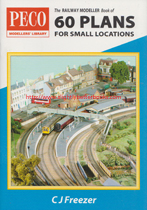
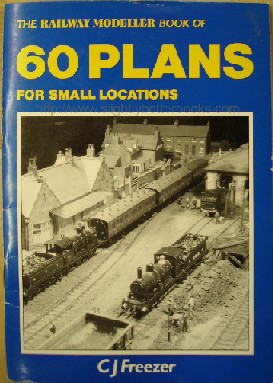
- The Railway Modeller Book of 60 Plans For Small Locations [top]
Written by Cyril J. Freezer
First
published in 1989 in Great Britain, by Peco Publications and Publicity Ltd, in paperback (staple binding) 32pp, no ISBN
Second impression: January 1992
Third impression: July 1993
Fourth impression: January 1996
Fifth impression: April 1999
Sixth impression: January 2002
Seventh impression: August 2007
Eighth impression: October 2009
Ninth impression: June 2014, in Great Britain, by Peco Publications and Publicity, Ltd., 33pp, ISBN 0900586257
Contents: The 9th impression of Cyril Freezer's classic book from Peco Publications of track plans in 4mm scale OO gauge for space-starved modellers has now been brought right up-to-date. Completely re-drawn, the plans take into account many of the changes which have taken place both on the prototype and on model railway layouts over the last 30 years (up to the time of publication in circa 1990). These include changes in operations, track layouts and types of traffic as well as the vastly increased range of equipment available to the modeller since the first edition some 32 years ago. New homes are, if anything, smaller than ever and these plans are designed to ge the most7 out of every square foot of space and include a section on genuinely portable layouts. Whether you have the previous editions or not, this new book is a must for all modellers.
The original book was a compilation of plans drawn for 'Railway Modeller' that fell into a loosely defined space limit, basically up to 8ft by 6ft maximum, or L shaped portable layouts and terminus plans. Three editions followed this first edition and because the layouts were getting tired (most were drawn pre-1960), it was decided to redo them to broaden the focus from layouts that were essentially steam age to layouts that you'd find more modern traction such as diesels and electrics running along.
As in the original books, a number of plans are shown on sectional baseboards, of which the basic unit is only 3ft long - the author believed that it was not sensible to use a module bigger than this because the railway model builder would not be able to safely carry this through the house (or other buildings), on their own, nor find a suitable storage space for larger pieces in the average house. Baseboards of up to 3ft in size are also much easier to transport in the average car.
Most plans have one side labelled 'FRONT', which is the side Cyril Freezer feels is more suitable for the operator under home conditions; and at exhibitions, the controls can be repositioned to let the public see the more interesting side.
Three plans have been included specifically for Continental layouts with two based on Swiss practice and the other more general. The section on fiddle yards has been expanded to better reflect the important role these played in post-war British model railway practice. Please note that pointwork has been set out to use Peco products because at the time of publication, this was the most readily obtainable range of ready-made track in Britain. The author has throughout quoted the minimum radius of the design, since this will affect the choice of rolling stock. The author thought that most readers would lean towards ready-to-run stock and has therefore chosen a 1ft 3in absolute minimum, with 2ft as the optimum choice where space is available.
Chapters:
1. Simple Beginnings
2. Eight Feet Wide
3. The Garden Shed
4. Continental Excursion
5. Into the Diesel Era
6. The Fiddle Yard
7. The Classic L
8. Minories
9. Narrow Gauge
10. The Portable U
11. Special Purpose
12. Country Termini
13. Branch Line
14. City Stations
15. On Exhibition
|
|
November 2013, Peco Publications, pbk (staple binding)
In stock, click image above to buy for £1.60, not including post and packing, which is Amazon's standard charge (currently £2.80 for UK orders; more for overseas customers)
Alternative online retailers to try:
Click here to access our prebuilt search for this title on Abebooks
Click here for our prebuilt search for any edition of this book on Alibris
Or click here to access our prebuilt search for this title on Ebay
Click here to access our prebuilt search for this title on Biblio
|
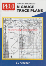
- The Railway Modeller Book of N Gauge Track Plans [top]
Written by Cyril J. Freezer
First published in January 1996 in Great Britain by Peco Publications and Publicity Ltd., in paperback (staple binding), 33pp
Second impression: January 2000
Third impression: June 2003
Fourth impression: February 2006
Fifth impression: June 2008
Sixth impression published in November 2013 in Great Britain by Peco Publications & Publicity Ltd., in paperback (staple binding), 33pp, ISBN 09000586508
About this book: The track plans in this book make use of baseboards which have long been found large enough for 00 gauge layouts, but which are also designed to fit into rooms of a size that can be found in a modern home. The rooms are based on the dimensions of spaces in houses in which the author has lived over the years on the reasonable assumption that others will be living in similarly sized homes, certainly across the United Kingdom.
When you come to what is often the only really available large space for a model railway in the house, the domestic garage can fit a lot of N gauge layout into it and still leave room for the car and if the reader has full use of the garage to build an N-gauge layout, then they will be able to build the sort of layout that over 4mm scale workers can only dream of!
All the plans in this book have been drawn on a computer using CAD (Computer-Assisted Design) and metric units. The squared grid is set at 150mm intervals, roughly 6 inches. The author has, however, given the overall sizes in both metric and imperial standards using the 'metric inch' of 25mm as the unit of conversion rather than the exact amount of 25.4mm because by the time the reader has measured the plans, they may have introduced errors into the layout to the order of half an inch. The key is to see this book as a collection of project plans.
The reader should set out their actual layout to full size on the baseboard or, if the reader prefers it, a large sheet of paper. Fitting the points into the layout is vital, so the reader is advised to use the Peco templates or the actual points themselves. Plain track can be fudged to fit, so long as too tight a curve is not introduced! With each plan, the object has been to fit the plan into the space specified. The author has erred on the conservative side with clearances and has worked to the given metric dimensions for the baseboards. Given that the imperial measurements are larger than the metric, the reader should find they have little trouble fitting everything in, if they prefer the older standards.
Contents:
Introduction
Solid Schemes
Layouts 1-5: 1.2m x 0.6m
Layouts 6-9: 1.95m x 0.75m
Above and Below Stairs
Layout 10: 1.8m x 0.9m
Layout 11: 1.35 x 1.725m
The smallest bedroom
Layouts 12-15: 2.4m x 1.95m
Diesel or Steam?
Layouts 16-17: 2.7m x 2.55m
An Awkward Room
Layouts 18-20: 3.3m x 1.95m
The Garden Shed
Layouts 21-23: 2.25m x 1.65m
With exhibition in mind
Layouts 24-26: 4.575m x 0.9m
Utilising the garage
Layout 27: 2.4m x 1.35m
Layout 28: 4.8m x 2.4m
Layouts 29-32: 4.8m x 2.7m |
|
2010, Peco, pbk
In stock, click image above to buy for £1.60, not including post and packing, which is Amazon's standard charge (currently £2.80 for UK orders; more for overseas customers)
Alternative online retailers to try:
Click here to access our prebuilt search for this title on Abebooks
Click here for our prebuilt search for any edition of this book on Alibris
Or click here to access our prebuilt search for this title on Ebay
Click here to access our prebuilt search for this title on Biblio |
- The Railway Modeller Book of Track Plans for Various Locations/The Modeller Book of Track Plans No.1 [top]
Written by C. J. Freezer
First published in 1989 in Great Britain in January 1989
Second impression in January 1992
Third impression in October 1994
Fourth impression in February 1997
Fifth impression in March 2000
Sixth impression in January 2003
Seventh impression in June 2005, published by Peco Publications & Publicity Ltd., in paperback, 36pp, ISBN 0900586109
Eighth Impression published in July, 2007 in Great Britain by Peco Publications & Publicity Ltd., in paperback
Ninth Impression published in February,
2010 in Great Britain by Peco Publications & Publicity Ltd., in paperback, 36pp, ISBN 0900586109
Contents: This book was first published in 1989 updating a publication from 16 years earlier and taking account of changes in the railway modelling hobby and in people's lifestyles. It includes over thirty plans drawn and described, ranging in size from 8' 6" * 6' 6" through 10' * 6' right up to 16' * 8'. Thought is given to the ways in which prototype railway development affects model railway design, and such subjects as train lengths, bi-directional running, diesel depots, etc. are discussed. Traditionalists and readers of the first edition will delight in the knowledge that the plan based on Exeter Central (pre-Beeching) is still included. Although many of the plans have been designed with 4mm scale OO gauge in mind, many will provide inspiration for those readers working in different scales.
How it relates to the earlier edition: Plans in the earlier booklets were designed to fit conditions that no longer existed in 1989. The author determined to revise the plans and incorporate fresh ideas combining the best of the old 'Track Plans' and 'Plans for Larger Layouts'; also working on a minimum radius of 2ft for visible tracks and 18 inches for hidden tracks, with greater accessibility throughout and, most importantly, a restriction to OO gauge since the author was already working on an N-Gauge book. He also confined himself to spaces one might find in and around the home; therefore all but one of the largest plans are meant for the garage!
Chapters:
Introduction
1. The Small Bedroom
2. Middle-Sized
3. Modern Image
4. Living with the car
5. Exeter Central
6. Filling the Garage
7. Transportable Schemes
|
|
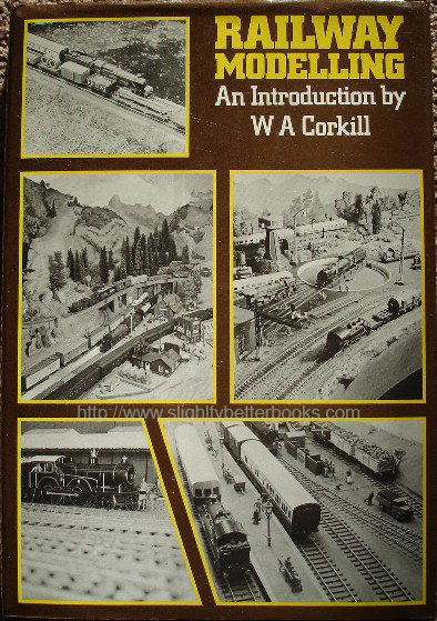
1980, David & Charles, hbk
In stock, click to buy for £2.95, not including p&p
Alternative online retailers to try:
Click here to access our prebuilt search for this title on Abebooks
Click here to access our prebuilt search for this title on Alibris
Or click here to access our prebuilt search for this title on Ebay
|
Contents/synopsis: With model railways today more popular than ever, and with a rapidly widening international range of complete models, kits and parts available, the newcomer is faced with a bewildering choice of equipment and systems. This introductory work presents beginners young and old with a wide-ranging survey of all the more important aspects of this fascinating hobby, looking at British, European and North American equipment and models, and comparing prototype with model features. It also serves as a valuable reference, with facts, figures and explanations in a crisp, economical style, by an author well versed in practical railway modelling. The many line illustrations are closely related to the accompanying text, and the detailed photographs show much that can be accomplished in realism and interest. Some of the examples portrayed are simple and inexpensive, while others are intended to encourage those more experienced with developing dedication and skill. Subjects affecting sound construction and efficient operation are dealt with in depth, while off-line scenery, buildings and accessories are described and illustrated at a level which can really bring an otherwise static layout to life.
Useful Notes:
The chapter 'At the Drawing Board' contains a useful table of scales A to P in mm/1ft for British gauges OO and HO, North American HO scale and Continental Europe HO scale. Also contains suggested layout drawings.
In the 'Civil Engineering' chapter, it provides diagrams (no measurements) of different types fo civil engineering structures you might find on a railway such as steel and timber trestle bridges. Fig 73 is useful in that it gives you the dimensions of plate girder bridges -average figures for bridges of light/heavy construction. Spans and dimensions are in feet. Diagrams of popular types of trusse bridges sit alongside basic tunnel mouth shapes and diagrams indicating how to create viaduct and underbridge features.
Chapters:
Introduction
1. Policies and Plans
2. Specifications
3. At the drawing board
4. Foundations
5. Trackwork
6. Civil Engineering
7. Scenery
8. Real Estate
9. Signals and Automatic Controls
10. Locomotives and rolling stock
11. Finishing Touches
12. Operation and Maintenance
Appendix 1: Graphical methods for scaling
Appendix 2: Electrical supplies and controls
Bibliography; Abbreviations; Index |
|
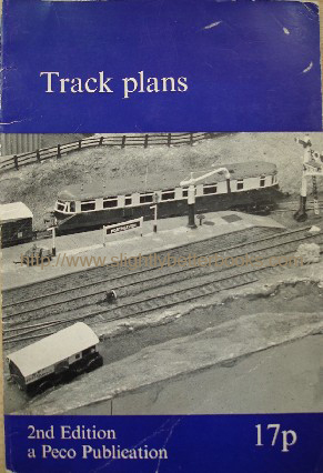
1973, Peco Publications & Publicity, pbk
Alternative online retailers to try:
Click here for our prebuilt search for this book on Abebooks
Click here for our prebuilt search for any edition of this title on Alibris
Click here for our prebuilt search for any edition of this title on Ebay |
- Track Plans [top]
Written by C. J. Freezer
First published in 1964-1970 (First Edition) by Peco Publications & Publicity Ltd
2nd Edition first published in July 1971 by Peco Publications & Publicity Ltd
Second impression published in November 1972 in Great Britain
Third impression (pictured left) published in August 1973
 in Great Britain featuring Dave Howsam's prize-winning 00 gauge layout of Porthleven station
About this book/synopsis: This book has no arbitrary track size limits set and the layouts range from the very small to the very large. Mainline themes predominate: in the 1970s, there is a fine selection of impressive large locomotives and the layouts have to be capable of handling them!
Chapters:
1) 6 * 4 and all that!
2) Extending the 6 *4
3) The Garden Shed
4) A Garage Scheme
5) Justifying two companies
6) Exeter Central
7) In disguise
8) The diminishing dumbell
9) Modern Image
10) The desirable maximum
11) Terminal Topics
12) Boxed In
13) Rabbits!
14) Mainly scenic
15) Small and simple |
|
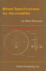
1978, OPC, pbk
In stock, click to buy for £10.20, not including post and packing, which is Amazon UK's standard charge of £2.80 (for UK buyers)
Alternative online retailers to try:
Click here to access our prebuilt search for this title on Abebooks
Or click here to access our prebuilt search for this title on Alibris
Or click here to access our prebuilt search for this title on Ebay
|
- Wheel Specifications for the Modeller [top]
Written and compiled by Mike Sharman, sourcing information from railway magazines, photographs, official records, specialist magazines and technical drawings and publications
First published in 1978 in Great Britain by Oxford Publishing Company (OPC) in paperback, 56pp, ISBN 0860930289
About this book: Now that the modeller is taking more notice of the details below the footplate, the author Mike Sharman felt that a 'Quick Reference' means of identifying some of the many different styles and sizes of wheel would be of interest. There are many hundreds of different styles and sizes and for the purpose of this booklet, they have been divided into main types and coded as shown in the illustrations on pages 6-7 in the section 'Wheel Type Code'. The period chosen is from British Railways steam back to about 1870, but as with all things historical, the author points out that there are grey areas which a work like this cannot hope to cover. The information presented is based on gleanings from the locomotive magazines of long ago, RTCS where available, on any photographs the author could find, and any drawings which have appeared in the specialist magazines over the years. The author asks that readers wishing to research to a greater depth bear in mind that every locomotive built between these periods will not be here as documentation is sketchy on the many methods of classification used, and the fact that many early locos were 'one offs' anyway, so the author has therefore tried to list the details as far as possible in an 'as built' state, hence the inclusion of most of the pre-grouping railways. The reign of the respective Chief Mechanical Engineers listed give a clue to the date built, but some machines appeared after the end of a reign, so were credited to their successors, and in many cases re-built by them, therefore the author has avoided rebuilds! Also, a locomotive credited to Stirling, for example, may have been built by outside contractors and therefore may not have the expected number of spokes and the crankpins in the same position. So, the reader should get a photo of the loco first before building it just to verify the details.
Reference is made to pre and post 1930 wheels and has come about by research showing a change of style around that period on some railways, notably the LMS and GWR. It was probably brought about by the need to strengthen the wheels to cope with the increasing loads which locomotives were being asked to pull. The problem with this type of change is that it means locomotives could have either the new or old sets on them, even if the locomotive was built after this change was introduced. Imagine the situation where a newer locomotive has been rebuilt (for whatever reason) and the wheels have been used from a scrapped locomotive... . The main structural difference involved moving the crankpin to sit between the spokes and then strengthening the spokes around the pin by blocking in some or all of the area of the nearest three spokes.
The book contains a very useful alphabetical list of Chief Mechanical Engineers for all the pre-Grouping and Grouping railways; and the tables for each of these railways gives for each CME, wheel arrangement and class of loco the date built, leading wheel dimensions, the leading wheel spokes; the driving wheel dimensions, the driving wheel spokes, the trailing wheel dimensions and the trailing wheel spokes, the crankpin size, the tender wheel dimensions and tender wheel spokes and any relevant notes
Contents:
Introduction
Wheel Type Code (a section or guide on how to use the tables of wheel specification data)
Chief Mechanical Engineers
LNER
North Eastern
Great Central
Great Eastern
Great Northern
North British
Great North of Scotland
Hull and Barnsley
Metropolitan
Southern
LSWR
LB and SC (London, Brighton and South Coast Railway)
South Eastern
LC
and Dover (London, Chatham and Dover)
South Eastern and Chatham
Isle of Wight
LMS
LNWR
Midland
Lancs and Yorks
North Staffs
Furness
Caledonian
Glasgow and South Western
Highland
North London
Midland and Great Northern Joint
Somerset and Dorset
London, Tilbury and Southend
Great Western
Barry
Cambrian
Cardiff
Rhymney
Taff Vale
Midland and South Western Junction
British Railways and the War Department |
|
Books and Magazines about Model Railways on Ebay Right Now! [top]
|